Contact:Mr. HaiJing Zhang
Cell:0086 136-6267 1007
Tel:008613692133093
Address:Bldg3 Puhua Science & Technology Park Tongsheng Community Dalang St Longhua Dist ShenZhen China
At present, people's material needs and cultural living standards are improving day by day, a variety of home appliances into thousands of households, among them, most household appliances have their own different remote controls, people often in order to control an electrical appliance and everywhere to find its corresponding remote control, so it brings a lot of inconvenience to people's lives. In order to solve this problem, this paper proposes a design scheme of a multi-function remote control: the remote control can have a remote control function for multiple electrical appliances through self-learning, that is, time-saving and labor-saving, so that people are free from the trouble of facing many remote controls at the same time.
Functions:
1.Suitable for coded infrared remote control household appliances;
2.Remote control of multiple household appliances;
3.It has a learning/control multiplexing key, 5~10 device selection keys, and 10~20 function control keys. A device selection key and each function control key jointly realize the control of a device;
4.The learning and control of common functions of multiple devices can be realized through a device selection key and various function control keys;
5.Low cost and strong anti-interference ability.
Principle:
The remote control is composed of infrared receiving and transmitting circuit, signal conditioning circuit, central controller 8031, program and data memory, keyboard and state indicating circuit.
The remote control has two states: the learning state and the control state. When the remote control is in the learning state, every time the user presses a control key, the infrared receiving circuit begins to receive an external infrared signal, and at the same time converts it into an electrical signal, and then after detection, shaping, amplification, and then the CPU regularly samples it, and the binary data of each sampling point is stored in a unit of 8 bits to the designated memory unit for future control of the device. When the remote control is in the control state, each time the user presses a control key, the CPU reads a series of binary data from the specified memory unit, and the serial output (the time interval between bits and bits is equal to the time interval when sampling) to the signal holding circuit, and at the same time the modulation circuit performs signal modulation, and the modulation signal is amplified and emitted by the infrared emitting diode, so as to realize the control of the function of the corresponding device of the key.
Part of the circuit design
Infrared receiver circuit
Press the learning/control key to switch the CPU to the learning state, at this time the learning status indicator D5 is lit, when pressing a device selection key, the program adjusts the data pointer (set by the program developer) so that it points to the starting unit of a specified length data area of the data memory, when pressing a control key of the remote control and a control key of the remote control to be learned at the same time, The 8031 will be programmed to output a low level to pin P3.1 (i.e., the JR terminal) (which the original initializer set to high), and the level signal at the JR terminal is or not the control level of gate U1A. When P3.1=0, the output of U1A is the inverting signal at the input. That is, the infrared receiving circuit composed of D1.U4 is responsible for receiving the signal sent by the learned remote control, when D1 has an infrared signal input, the signal is demodulated, shaped, amplified by U4 (this decoding pulse is out of phase with the original coding pulse) by 7 pins, Through or non-gate U1A reverse input to the P1.4 pin of 8031 through the IN pin, the first high-level pulse of this signal to C4 quickly charged (reasonable selection of R3, R4 parameters to prevent repeated triggering), while through the IT pin of U2A to the INT1 pin of 8031 to send a falling edge signal, after the CPU responds to the interrupt, the IN infrared encoding signal of U1A is regularly collected from P14 to form a series of binary digits, and stored in 8-bit units to the specified device, Specify the data area of the key (error verification can be performed by firing a code burst) to complete the learning of a key. If you learn the functions of other keys, the method is the same. If you want to learn the functions of each key of another device, press the other device selection key of this remote control, and then press each function control key respectively, so as to learn the functions of the remote control to be learned.
Infrared transmitter circuit
Press the learning/control key to switch the CPU to the control state, while the control status indicator D6 is lit, press a device selection key, the system will be in the control state of a certain device, and then press a function control key, the system is addressed by the device number and function key number, and finds the data storage area address of the corresponding function key of the corresponding device (these data are collected from the time of learning the function of the key), and read out these data in turn, The CPU controls the output to the OUT pin of the modulation circuit U2B through the P1.5 pin in turn in bits (the time interval is the same as the sampling interval), and passes through the U2B, U2C, C5. R7. After the modulation circuit composed of R8 is modulated (the modulation frequency is 38KHZ), it is amplified by Q1 and drives D4 to output the infrared remote control signal to realize the control of a function of the selected equipment.
Overview of other circuits
This part of the circuit includes learning, control indication circuit, data, program storage circuit, keyboard circuit, etc. The learning and control indication circuit is indicated by a light-emitting diode, and the control signal is output by the P1.6.P1.7 pin of the 8031, and then driven by the amplification circuit D5.D6 respectively; the device number display circuit uses a digital tube static display; the keyboard circuit adopts a query scanning keyboard; the program memory adopts common ROM or EEPROM, and the data memory can use a relatively inexpensive random electrically erasable memory compatible with 6264 or 62128.
This design is only suitable for infrared remote control equipment of code division system, and does not involve frequency division infrared remote control equipment and frequency modulation signal is non-38kHz infrared remote control equipment, such as to expand the functions of the remote control, as long as the frequency measurement circuit is added to the infrared receiving circuit, and the numerical control signal generator is used in the infrared emission circuit as a modulation circuit.
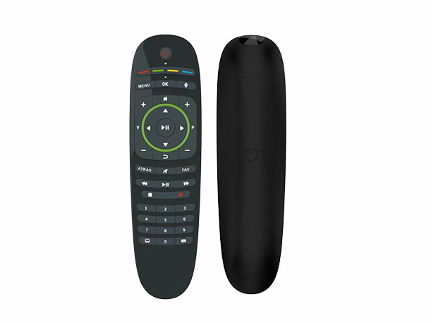
Car DVD special infrared remote control, full key is 40 keys, touch panel, good hand feel, use 2025 button battery.
 WhatsApp
 Wechat
Copyright © 2018-2022 Shenzhen KGYG Electronics Co., Ltd. ICP:粤ICP备18007551 Sitemap(BaiDu / Google)Technology:Qihuli
WechatCell


admin
There are no comments for this content